30 Oct Mitor 2012-2014
Laboratory simulation of planet-solar wind and interstellar medium/heliosphere interaction
We explore the feasibility of conducting a small-scale laboratory experiment to simulate the interaction between the solar wind and a planetary magnetosphere within the low-energy laboratory facilities at Torino and Milan Politecnico. These facilities previously hosted a series of experiments (2010–2012) focused on the hydrodynamics of hypersonic jets under stellar similitude conditions.
The initial phase of this project involves collaborative determination of the experimental parameters. Drawing upon the extensive expertise of the MIT team in heliospheric plasma measurements, we will establish the foundational setup for the experimental apparatus. Plasma parameters will be informed by spacecraft observations, utilizing data from the Voyager mission database accessible to MIT researchers.
Researchers at POLITO and POLIMI will assess the practicality of the proposed MIT experimental design, proposing modifications to the existing facility to achieve the following objectives: (A) generation of a cold plasma jet, into which a magnetic sphere representing the planetary magnetosphere will be introduced; (B) design and integration of an internal magnet system within the planetary model.
Complementary numerical simulations will be conducted at both MIT and POLITO to optimize experimental conditions. These computational tools will also play a critical role in interpreting the experimental results alongside in-situ spacecraft data, ensuring a comprehensive understanding of the plasma-magnetosphere interaction.
Participants:
MIT Kavli Center for Astrophysics and Space Science:
- J. D. Richardson
Politecnico di Torino:
- D. Borgogno
- D. Tordella
A substantial fraction of the universe is made up of magnetized plasmas. Examples near our solar system are the solar wind, planetary magnetospheres, and the local interstellar medium that surrounds our heliosphere. Models and observations show that when these plasmas collide, for example, when the solar wind runs into a magnetosphere or the local interstellar medium runs into the heliosphere, asymmetries in the flow and obstacle (the structure of the bow shock and magnetopause) result. For example, when the solar wind runs into Earth’s magnetosphere, the dusk side is usually pushed in more than the dawn side. The Voyager spacecraft discovered that the heliosphere is also asymmetric; the termination shock at Voyager 2 is 10 AU closer to the Sun than at Voyager 1. These asymmetries are hypothesized to result when the magnetic field direction in the flow is tilted from the flow direction (this tilt averages 45 degrees at Earth). Models predict that in this situation, the magnetic field drapes around the obstacle so that the magnetic pressure is higher on one side than the other, creating the asymmetry, see Fig.1.
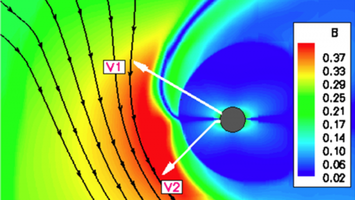
Figure 1: Simulation of the interaction between the heliosphere and interstellar medium [Opher et al., 2006]. The interstellar medium flows in from the left, and the magnetic field lines are at an angle to the flow as shown. This angle causes the field lines to drape around the heliosphere asymmetrically, pushing into the heliosphere in the south. A similar asymmetry should be produced in Earth’s magnetosphere.
We carried out a laboratory experiment to simulate this basic process in a controlled environment. This experiment allowed us to systematically change the flow and magnetic field and measure the asymmetry that results. The experiment consists of a hypersonic plasma jet (simulating the solar wind) flowing past a spherical body with a magnetic field (simulating both the Earth’s magnetosphere and the inner part of the heliosphere). To make the experiment relevant, we replicated in the experiment three observed solar wind parameters. Two are dynamic, the Mach number of the flow and beta, the ratio between the thermal pressure and the magnetic pressure. The third is geometric, the inclination of the magnetic field lines in the plasma flow to the dipole axis of the spherical body and to the velocity flow direction. These parameters will be varied in the experiment to cover the range of values observed in the solar wind. We then predict the asymmetry of a magnetosphere based on the upstream solar wind or use the observed asymmetry of the heliosphere to determine the possible interstellar medium magnetic field. We conducted this experiment in the facility of the Politecnico di Milano, which is used to simulate astrophysical jets and produce insights into their long-term hydrodynamics and evolution, see http://iopscience.iop.org/1367-2630/13/4/043011. For this project, a hypersonic beam (Mach numbers 10-20) was ionized and magnetized as it exited the nozzle. Plasma betas will be varied between 0.1 and 1. A spherical obstacle with a dipole field inserted into this magnetized supersonic flow. An external magnetic field is used to incline the magnetic field to the flow direction, as in the solar wind. The flow lines from this configuration will be captured with a fast camera. The position of these flow lines tell us the shape of the obstacle and the magnitude of the dawn-dusk asymmetries created by the flow.
– The POLIMI-POLiTO (Politecnico di Milano and Politecnico di Torino) facility.
The facility is a system that was specifically designed for the study of hypersonic jets. The system consists of a cylindrical vacuum vessel equipped with suitable nozzles and an electron gun that makes it possible to digitally image fluorescent plane sections of the jets with a charge-coupled device (CCD) color camera. The setup inside the vessel is sketched in Fig. 2. Data on the experimental system are shown in Table I. A laboratory view of the facility is in Fig. 3.
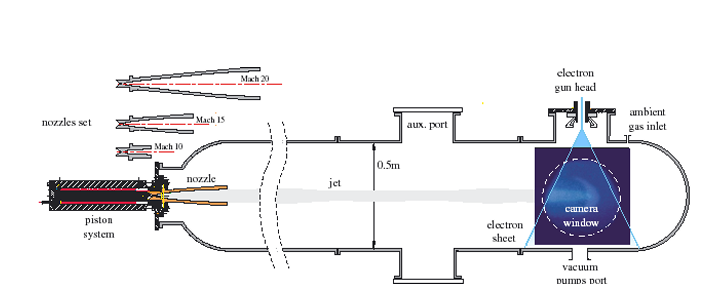
Figure 2. Experimental setup. The vessel is modular; five different sections are available for mounting, and the total length can vary from 1.4 to 4.1 m, with a constant diameter of 0.5 m. As shown on the left, a set of de Laval nozzles can be used. All the nozzles have the same converging section and throat (radius = 1 mm), whilst the diverging section depends on the Mach number of the design. The output radii are 12.0, 35.7, and 60.9 mm
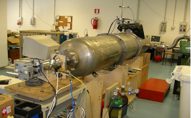
Figure 3 – Picture of the vacuum vessel and piston system producing the gas stagnation conditions.
Hypersonic jet flows can be obtained by means of both de Laval and truncated sonic nozzles. The jets propagate along the longitudinal axis of a cylindrical vacuum vessel. We can use different gases for the jet and the surrounding ambient gas in the vessel, and we can vary the density ratio between the jet and ambient gases. The gases involved in these experiments are helium, argon, xenon, and air. The vessel is modular; five different sections are available for mounting, and the total length can vary from 1.4 to 4.1 m, with a constant diameter of 0.5 m. The gas flow in the nozzle is driven by a fast piston system to produce the desired gas stagnation conditions, see Fig. 4. An electron gun, equipped with a deflection system, creates an electron sheet. This sheet intercepts the jet and generates a plane fluorescent section of the flow, which is then acquired by a fast CMOS camera equipped with an image intensifier. The vacuum chamber is modular, which makes it easier to mount, test, and adjust the new hardware. The different new parts can be preliminarily and independently tested outside the chamber.
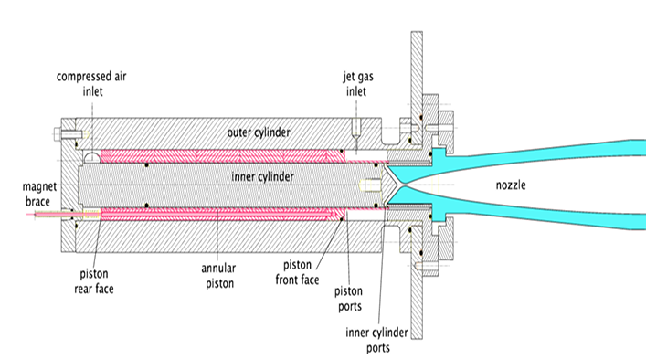
Figure 4. Scheme of the piston system.
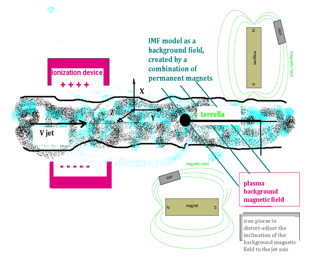
Figure 5 – Conceptual scheme for the modified experimental setup
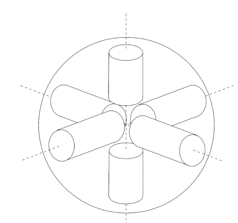
Figure 6 – Scheme for the Terrella inner system of magnetic dipoles. By varying the characteristics of the dipoles inside the Terrella, the shape, intensity, and inclination of its magnetic field can be changed with respect to those of the plasma flow.
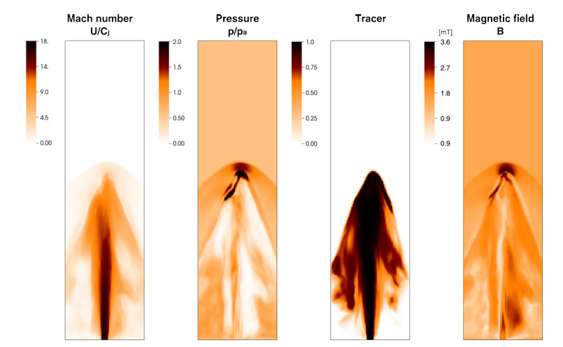
Figure 7.Visualization of the Helium jet interacting with a uniform lateral magnetic field of intensity 1.6 mT. The initial ionization is 0.1 %. The initial magnetic field in the jet is 0.14 mT. Mach = 18. Pressure in the vacuum chamber is 2.5 Pa, initial density in the jet is 2.7×10⁻⁴ kg/m3
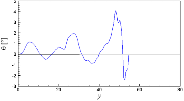
Figure 8. Snapshot at t=14.5 of the Helium jet in figure 7. Lateral deviation (in the yz plane) of the jet velocity along the axis y is computed as atan (Vz/Vy). By excluding the jet head front shock (45 < y< 55), the average value is about one degree.
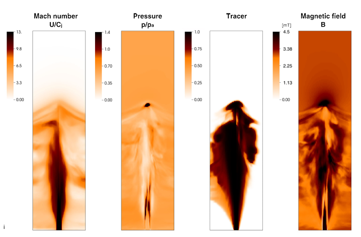
Figure 9. Visualization of the Xenon jet interacting with a uniform lateral magnetic field of intensity 3 mT. Initial ionization 0.1 %. The initial magnetic field in the jet is 3 mT. Mach = 15. Pressure in the vacuum chamber, 9 Pa, initial density in the jet 9.3×10⁻³ kg/m3.
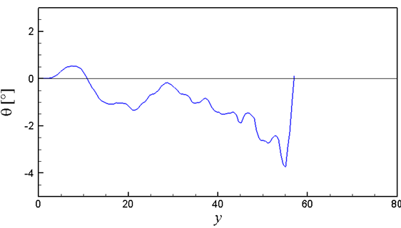
Figure 10. Snapshot at t= 15.5 time scales of the Xenon jet in figure 9. Lateral deviation (in the yz plane) of the jet velocity along the axis y is computed as atan (Vz/Vy). By excluding the jet head front shock (52 < y< 60), the deviation average value is about 1.5 degrees.