04 Nov Collision Detection Alogrithm
Collision detection alogrithm
A major problem in the inertial particle/droplet module is the detection of collisions between the particles. With Np particles, the detection of binary collisions requires O(Np2) operations. Therefore, the search for collisions is done in smaller portions of the domain (each cell will contain fewer particles reducing the number of operations).
The collision detection algorithm is organized in the following four stages:
First Collision detection

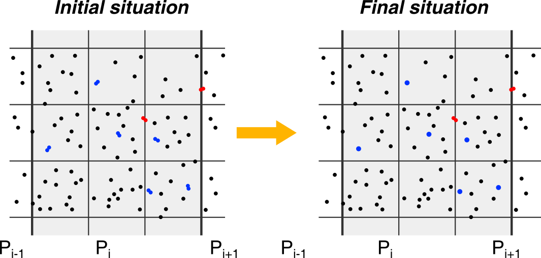
The domain belonging to each core is divided in cells (the grey area indicates the part of the domain assigned to core Pi) thick lines indicate the frontier between the regions distributed to different cores, and thin lines are the frontier of the cells). In each cell, the algorithm looks for binary collisions. In this stage only the collisions where both particles belong to the same cell can be detected (blue ones), but not the collisions where particles belong to different cells (red ones). In the image, it is assumed that particles coalesce.
Particle transfer (shift of the domain decomposition for droplets)

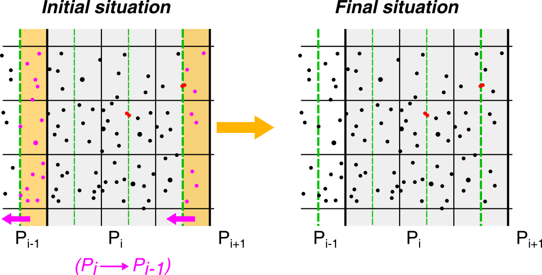
The partition of the domain is shifted by half cell in one direction (green lines indicate the original domain partition). After this shift, colliding couples which where at the interface between two cells are no more at the interface and the collision can be detected. When the direction of the shift is distributed, this step requires that each core transfers the particles enlightened in violet to the neighboring core (from the core “i” to “i-1”).
Second collision detection
The detection is carried out in each subdomain as in step 1. (again, coalescence in assumed in the figure. The green lines represent the original partition of the domain)
Particle transfer (back to the original domain decomposition for droplets)

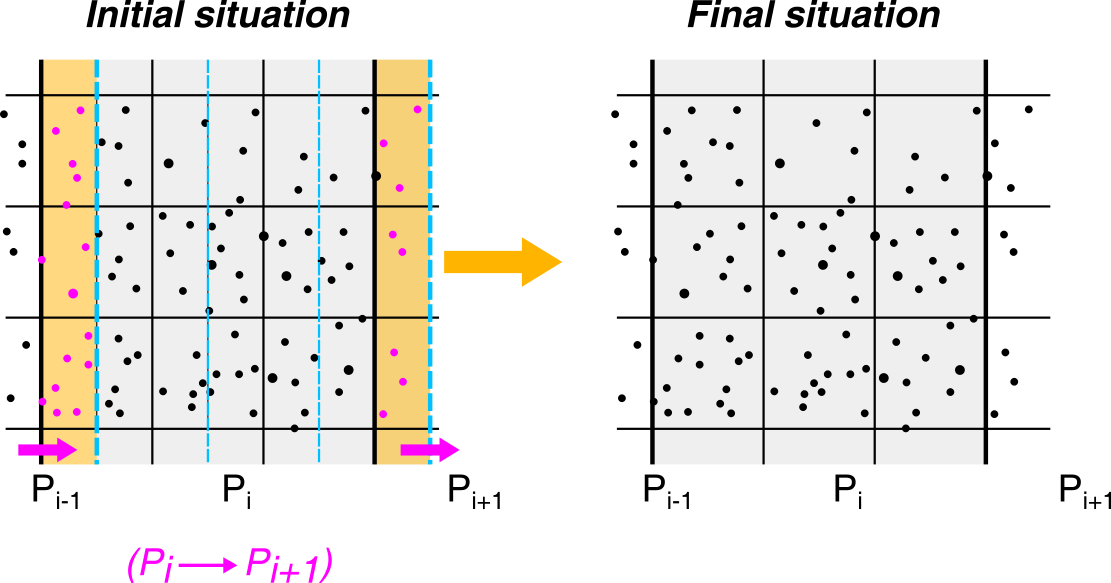
The domain partition is shifted again by half cell (in the opposite direction as in step 2), going back to the original domain distribution among the cores. Again, if the direction is distributed, communication between cores occurs (now from core “i” to “i+1”). Steps #2-#4 need to be repeated for each spatial direction.
Note: only droplets/particles are moved among the cores in this module. The fluid velocity (and temperature and water vapour) fields are not affected.
Note: in principle, step 3 can allow the detection of multiple collisions.


